The die-type list most suppliers publish is really a list of applications. The decision that determines your cost, your lead time and your achievable cut-depth window is one level up: how is the cutting edge actually held on the cylinder?
Rotary die cutting is a continuous process. The tool cylinder rotates in register with an anvil cylinder, and the web or sheet passes between them. Because the tool never lifts, throughput is high and cut depth is set once by the gap between the cylinders rather than re-established on each stroke. Everything that follows is about how that tool cylinder is made.
GB standard reference
- Standard
- GB/T 1299 (alloy tool steel) · GB/T 1220 (stainless)
- GB grades in this article
- Cr12Mo1V1 · Cr8Mo2SiV · W6Mo5Cr4V2 · W6Mo5Cr4V2Co5 · W2Mo9Cr4VCo8 · PM23
- Also sold as
- SKD11 / D2 · DC53 · M2 · M35 · M42 · ASP23
- Hardness range
- HRC 58-62 cold work · HRC 60-66 high-speed steel
1. The Six Construction Families We Machine
Every rotary cutting tool in our range falls into one of six families. They sit on a single continuum: at one end the cutting edge is part of the cylinder itself and nothing can move, and at the other end the edge is carried on separate elements that can be replaced individually.
| Family | How the edge is held | Best fit | Repair route |
|---|---|---|---|
| Solid engraved | Machined into a one-piece body | Repeated pattern and shape contours | Re-machine the contour |
| Segmented | Replaceable hardened segments on a body | Intricate or long contours, corrugated | Replace one segment |
| Spiral cutting | Continuous helical groove in the body | Cross-cutting, perforating thin webs | Re-grind the helix |
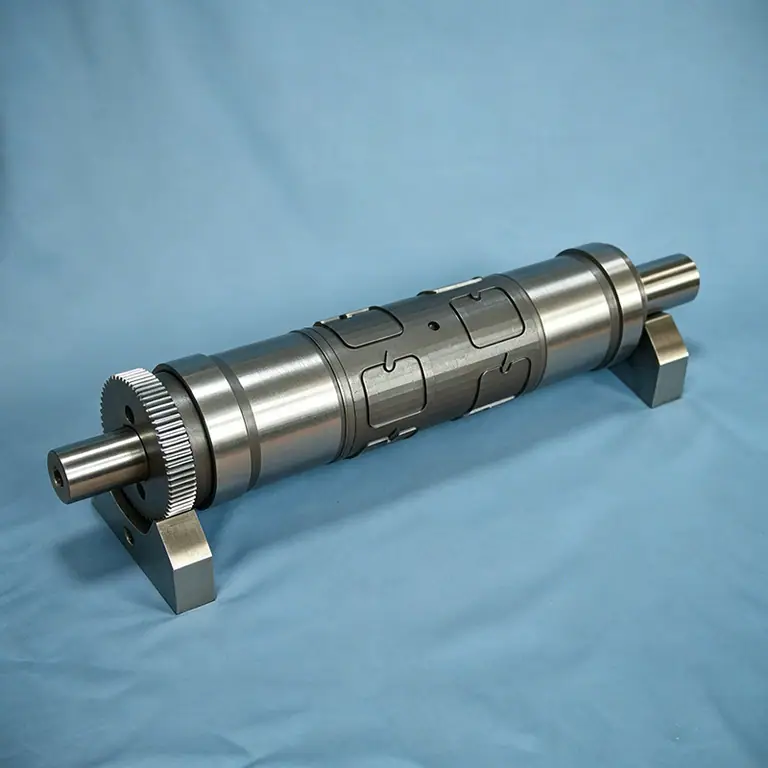
| Gear-driven | Gear-registered body with inset inserts | Registered cuts against print stations | Replace the inserts |
| Slitting assembly | Cutting rings on a common shaft | Multi-slit, score and perf lines | Replace an individual ring |
| Complete roller | As above, plus journals and end plates | Drop-in replacement for a press station | Reface, or replace worn parts |
2. Solid Engraved Dies
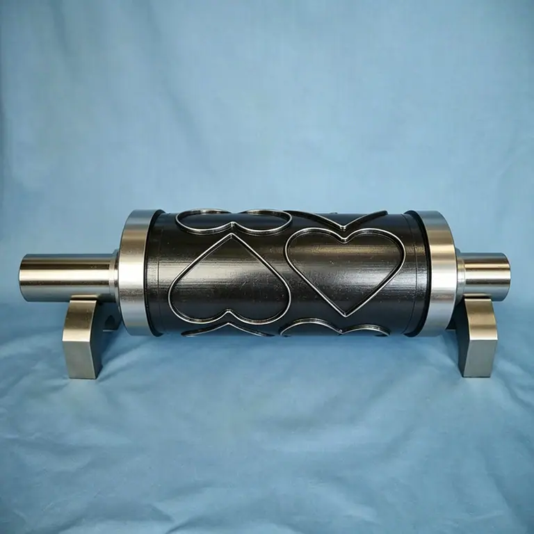
In a solid engraved die the cutting contour is machined directly into a one-piece hardened steel cylinder, leaving a raised edge on a solid body. There is no plate to shift, no assembly clearance and no joint to move, so this family holds the tightest cut-depth window of the six — which is exactly why high-volume label work and long-run carton work runs on it.
- Typical outside diameter
- Φ25 - Φ200 mm
- Face length
- up to 650 mm
- Radial runout of cutting edge
- ≤ 0.01 mm
- Tooth height tolerance
- ±0.005 mm
- Edge hardness
- HRC 60-66 depending on grade
- Gear registration
- Matched pairs, backlash measured
2.1 Why the gear and the contour must share a datum
The die gear drives the cylinder in register with the anvil, so any angular error between the gear teeth and the cutting contour turns into a cyclic variation in where the edge lands. At high web speed that shows up as cut-depth ripple — one label kissed perfectly and the next cutting through its liner. The practical rule is that the gear and the contour are cut from the same datum on the same machine, and the die is balanced after grinding so that imbalance does not reintroduce the ripple dynamically.
3. Segmented Dies
A segmented die divides the cutting contour into individual hardened segments mounted on a reusable steel body, retained by screws, dowels or a wedge system. This is the standard answer for two problems: contours too intricate or too long to machine as a single piece, and tools where a damaged section should be replaced rather than the whole cylinder re-machined.
A segmented die is only as good as its segment fit. Every segment must sit at the same height to within microns, or the tool leaves shadow marks where one segment cuts deeper than its neighbour. Preload, dowel position and body flatness all matter more than the segment's own hardness.
- Intricate or long contours become manufacturable in pieces rather than one impossible solid
- A worn or chipped segment is re-ground off the machine or simply replaced
- The body is a long-life asset — you buy segments, not cylinders, on repeat jobs
- Segment materials can be chosen individually, so the highest-wear area can use PM23 while the rest uses W6Mo5Cr4V2Co5
4. Spiral Cutting Dies
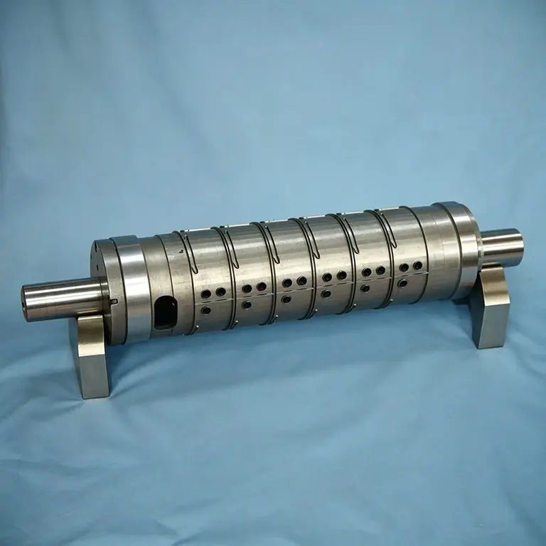
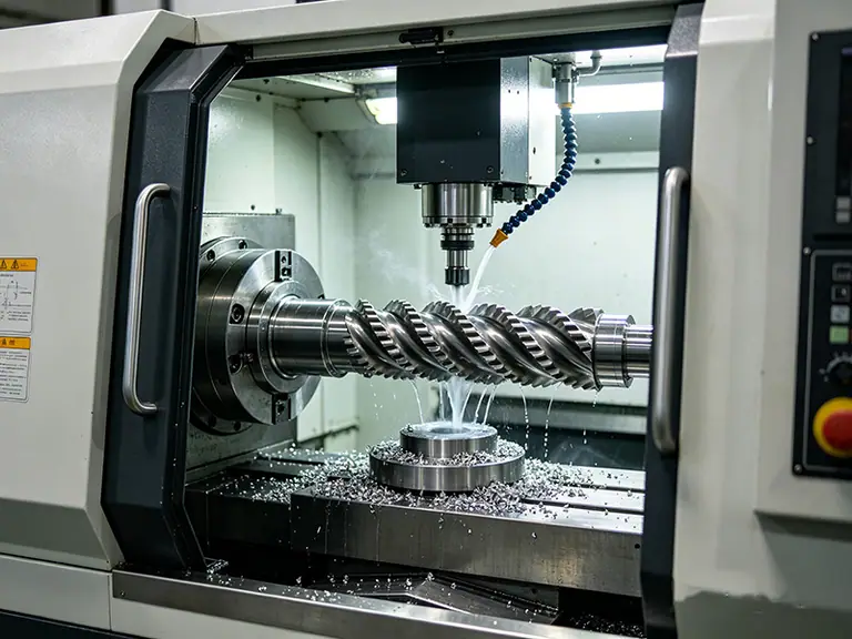
A spiral or helical die carries a continuous groove machined around the cylinder body, producing an uninterrupted cutting edge that wraps the face. The important consequence is mechanical rather than metallurgical: the cut is progressive instead of simultaneous across the whole face, so peak cutting force drops sharply.
That lower peak force is what lets a spiral die cross-cut thin, brittle or slippery webs at speed without snatching or snapping them. It also runs quieter and with less vibration than a straight cross-cut, which matters on wide, fast lines. The trade-off is that the geometry has to be matched precisely to the web speed, or the cut staggers across the repeat.
| Characteristic | Straight cross-cut | Spiral / helical cut |
|---|---|---|
| Cutting action | Whole width at once | Progressive along the face |
| Peak cutting force | High | Substantially lower |
| Effect on thin or brittle webs | Can snatch or snap | Cuts cleanly at higher speed |
| Noise and vibration | Higher | Lower |
| Geometry tolerance | Forgiving | Must match web speed precisely |
5. Gear-Driven Profile Dies
A gear-driven die carries a ground drive gear together with inset profile cutting blocks. Where a plain cylinder relies on friction and setup to hold position, the gear locks angular position to the anvil and the print stations, so the contour lands in exactly the same place on every revolution. This is the family to specify when the die cut has to register to printed artwork.
The design consequence is that the gear and the contour must be cut from one datum. Errors between them appear as a periodic ripple in cut depth and register — and because the error repeats once per gear tooth, it is often misdiagnosed as a pressure problem at the press.
6. Slitting Blade Assemblies
When the job is slitting rather than shape cutting, individual hardened rings are mounted along a common shaft and set to the finished slit widths. A single assembly produces every slit in one pass. Because the rings are separate elements, one dull or chipped ring is re-ground or replaced on its own rather than scrapping the assembly — which is what makes slitting lines economical to keep running.
7. Complete Rotary Die Rollers
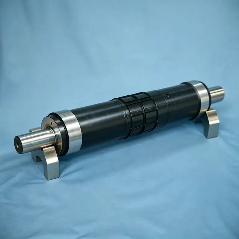
The last family is not a different cutting principle but a different scope of supply: the finished tool rather than just the cutting body. Hardened and ground bearing journals, end plates, the ring and insert assembly and the mounting register are all machined and verified as one referenced unit, then dynamically balanced. It arrives ready to drop into the press station.
This is usually the right way to specify a replacement for a tool that already exists. The one thing to get right up front is the journal dimensions and station register, because those have to match the machine you are putting it into.
Magnetic cylinders with thin flexible die plates are widely used for short-run label work, but we do not manufacture them. Our range is solid, machined tooling only — which means the cut-depth window and the resharpening budget you get are those of a machined cylinder, not a consumable plate.
8. Cutting Materials for Each Family
The same grade logic applies across all three families, with one addition: for segmented tooling, high-alloy steel, powder metallurgy steel and tungsten carbide are all used for the cutting segments, and the same materials can serve as anvil material. Coatings — hard chrome, ceramic or DLC-type low-friction layers — reduce wear and stop sticky materials building up on the rake face.
| Grade | Hardness | Where it belongs |
|---|---|---|
| Cr12Mo1V1 | HRC 58-62 | Standard and mid-range dies, robust geometry |
| Cr8Mo2SiV | HRC 60-62 | Where toughness prevents edge chipping |
| W6Mo5Cr4V2 | HRC 60-63 | General high-speed rotary cutting — best toughness in the class |
| W6Mo5Cr4V2Co5 | HRC 63-66 | Long runs where edge temperature limits life |
| W2Mo9Cr4VCo8 | HRC 65-66 | Abrasive film and thick board |
| PM23 | HRC 64-65 | Fine-pitch contours that micro-chip at coarse carbides |
| Tungsten carbide | — | Very high volume, or where wear is extreme and impact is low |
9. Choosing Between the Families
Work from the constraint that hurts most, not from the price list. The table below maps the usual production situations to a construction family.
| Situation | Choose | Because |
|---|---|---|
| Repeated pattern contour, high volume | Solid engraved | Stable one-piece body, tightest cut-depth window |
| Intricate or long contour, needs repairability | Segmented | Manufacturable in pieces; one segment replaceable |
| Continuous cross-cutting of thin webs | Spiral cutting | Progressive cut keeps peak force low |
| Register must be held to printed artwork | Gear-driven | Gear and contour cut from one datum |
| Several slits at exact widths in one pass | Slitting assembly | Rings set to finished width; individually replaceable |
| Corrugated board above ~2 mm caliper | Segmented on a solid body | Segments absorb impact, body survives |
| Fine-pitch contour with thin tooth roots | Solid engraved in PM23 | Uniform carbides resist micro-chipping |
10. Cost Per Impression, Not Cost Per Die
Families differ in first cost by a wide margin, which makes the purchase decision look obvious in one direction. Cost per impression tells a different story. A solid engraved die costs more than a segmented tool, but it needs no segment matching at make-ready, it holds a tighter cut-depth window throughout its life, and it can be refaced several times. Over a long run its cost per thousand impressions is frequently the lowest of the six — and it removes make-ready and unplanned stoppages from the schedule.
Buy construction for the run length and the tolerance window, buy the grade for the failure mode, and buy the coating for the substrate. Getting those three in the right order is most of rotary die specification.
Rotary die construction: frequently asked questions
A solid engraved die, because there is no joint. Nothing can shift or sit at a slightly different height, so the cut-depth window is both tighter and more stable over the tool's life. Segmented tooling can come very close if segment height matching and preload are controlled properly, but it depends on how well the assembly is built and maintained.
For a construction recommendation on a specific job, send us the die drawing, the substrate and caliper, the press make and model, and the run length between resharpens. Our engineers will tell you which family fits — including when the answer is not the one you expected.