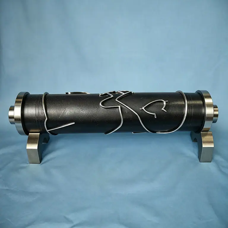
Solid, segmented and matched die-and-anvil tooling machined to drawing · W6Mo5Cr4V2 to PM23 · hardness uniformity ±1 HRC
Rotary Die Types by Construction
Six tooling families cover our rotary die range. Which one applies depends on the contour, the run length and how you want to handle a worn or damaged edge.
HRC 60-66
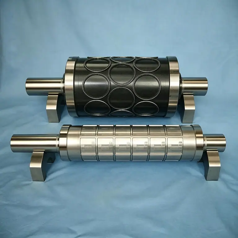
Solid Engraved Rotary Die
One-piece engraved cylinder · integrated contour
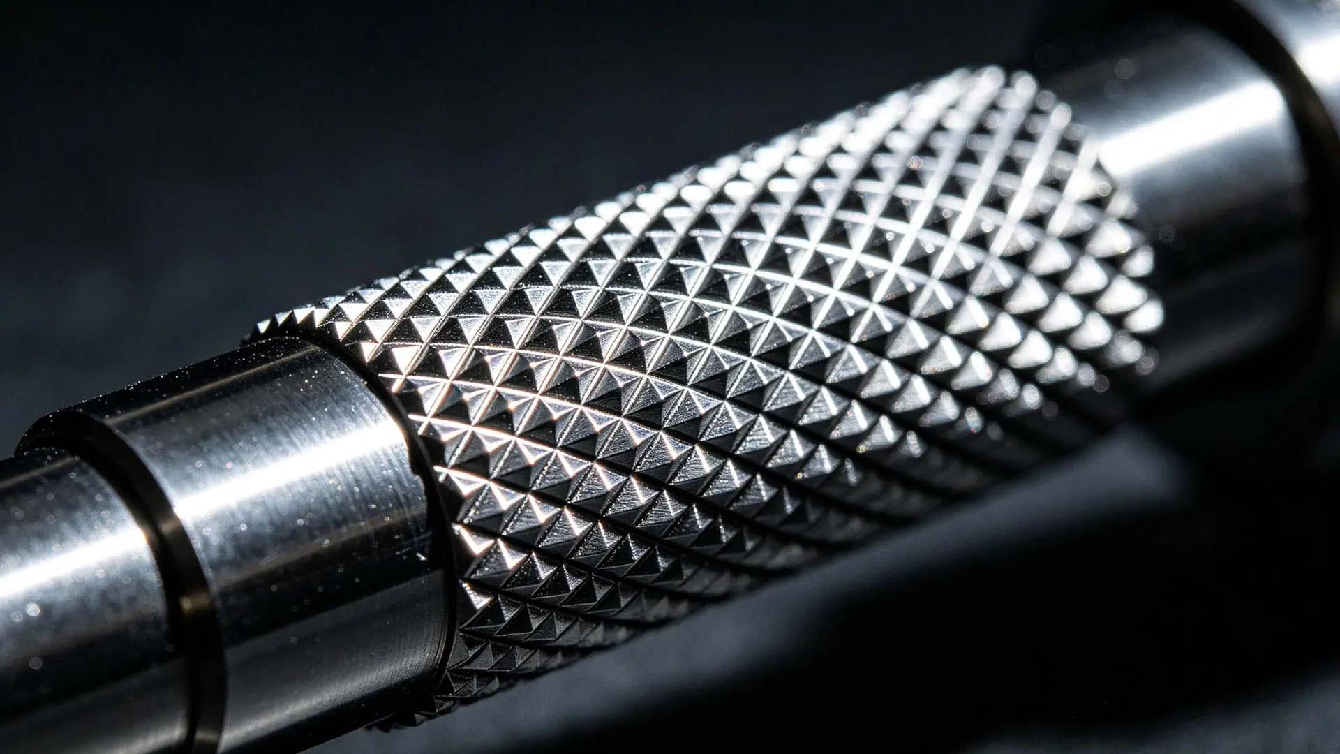
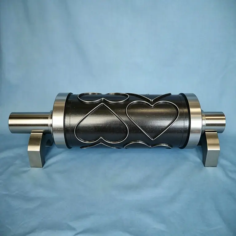
The cutting contour is engraved or milled directly into a one-piece hardened steel cylinder, leaving a raised cutting edge on a solid body. There is no assembly clearance and no joint to move, so this family holds the tightest cut-depth window — which is what a reliable kiss-cut depends on. Shown here cutting repeated pattern contours for label work.
Material
W6Mo5Cr4V2 / W6Mo5Cr4V2Co5 / W2Mo9Cr4VCo8 / PM23
Typical run length
500k - 5M+ impressions
High-volume label kiss-cuttingPattern and shape die cuttingLong-run carton and board
Best dimensional stability — one piece, no joint clearance
Resharpens many times before reaching minimum diameter
Handles the highest line speeds and the tightest cut-depth windows
Highest first cost of the families
A single damaged tooth means re-machining the whole contour
Longest lead time, because the contour is cut after hardening
HRC 62-66
Segmented Rotary Die
Segment die · inserted-segment cylinder
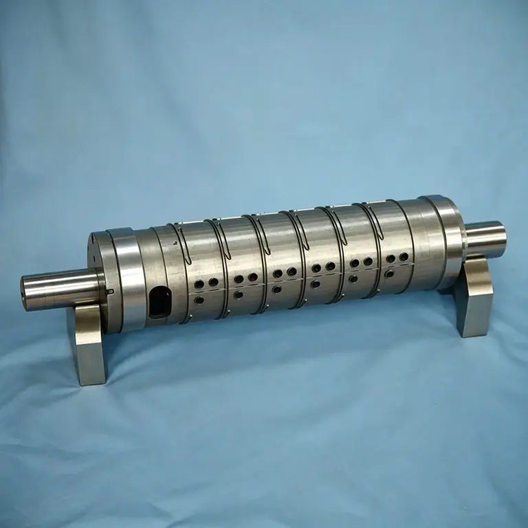
The cutting contour is divided into individual hardened segments mounted to a reusable steel body, held by screws, dowels or a wedge/keeper system. This is the standard answer for contours that are too intricate or too long to machine as one piece, and for tools where a single damaged section should be replaced rather than the whole cylinder re-machined.
Material
W6Mo5Cr4V2 / W6Mo5Cr4V2Co5 / W2Mo9Cr4VCo8 / PM23
Typical run length
Millions of sheets; body outlives many segment sets
Corrugated board up to 650 mm faceRepeat runs on a reusable bodyMulti-spec small-batch runs
HRC 60-66
Spiral Cutting Rotary Die
Helical die · ring-groove cylinder · cross-cut roller
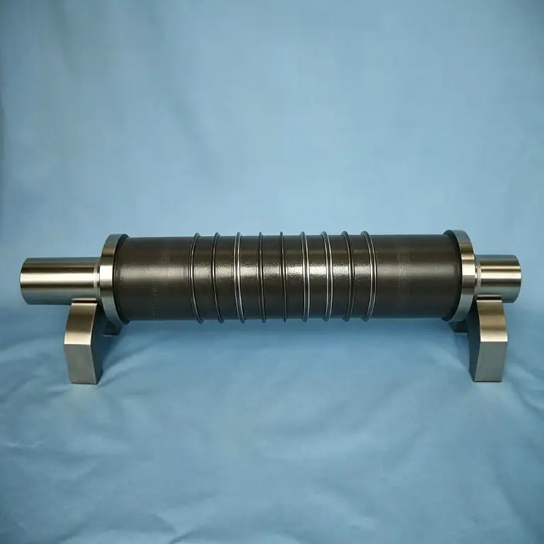
Continuous helical or ring grooves are machined around the cylinder body, producing an uninterrupted spiral cutting edge. Because the cut is progressive rather than simultaneous across the full face, peak cutting force is much lower than a straight cross-cut — which reduces web snap and lets the die run at higher line speed on thin or brittle stock.
Material
W6Mo5Cr4V2 / W6Mo5Cr4V2Co5 / W2Mo9Cr4VCo8 / PM23
Typical run length
Long runs; progressive cut reduces peak load
Continuous cross-cuttingSlitting and perforating rollsThin film and paper webs
HRC 60-66
Gear-Driven Profile Rotary Die
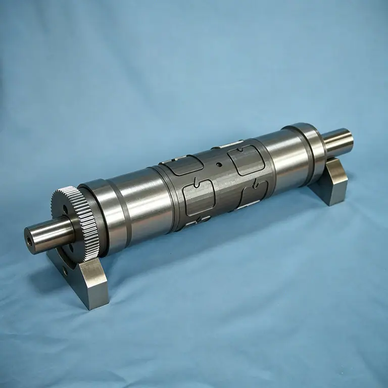
Geared die cylinder · registered profile die
A solid die body carries a ground drive gear together with inset profile cutting inserts. The gear sets angular position against the anvil and the print stations, so the contour lands in the same place on every revolution. Cutting the gear and the contour from a single datum is what makes the register repeatable.
Material
W6Mo5Cr4V2 / W6Mo5Cr4V2Co5 / W2Mo9Cr4VCo8 / PM23
Typical run length
High volume, repeat orders
Registered die cuttingPrinted label and carton workMulti-station in-line converting
HRC 62-66
Slitting Blade Assembly
Slitting roller · multi-ring cutter · score and slitting module
Individual hardened cutting rings are mounted along a common shaft, held by spacers or segment carriers. Each ring is set to the finished slit width, so a single assembly produces every slit in one pass. Rings can be re-ground or replaced individually, which keeps the cost of keeping a slitting line running low.
Material
W6Mo5Cr4V2 / W6Mo5Cr4V2Co5 / W2Mo9Cr4VCo8 / PM23
Typical run length
Long runs; individual rings replaceable
Multi-web slittingScore and perforation linesFilm, foil and paper converting
HRC 60-66 on cutting surfaces
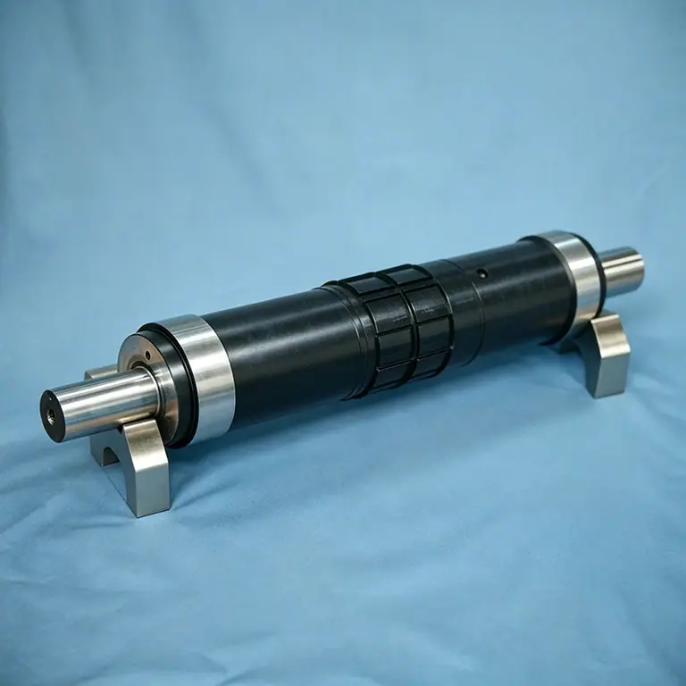
Complete Rotary Die Roller
Journalled die cylinder · ready-to-mount die assembly
The finished tool, not just the cutting body: hardened and ground bearing journals, end plates, the ring and insert assembly, and the mounting register all machined and verified as one unit. It arrives dynamically balanced and ready to drop into the press station.
Turnkey press stationsRetrofit and replacement diesShipment as a complete unit
Construction details from the shop floor
Additional builds showing features that matter at make-ready: segment fixing and preload, and complex free-form contour cutting.
Segmented
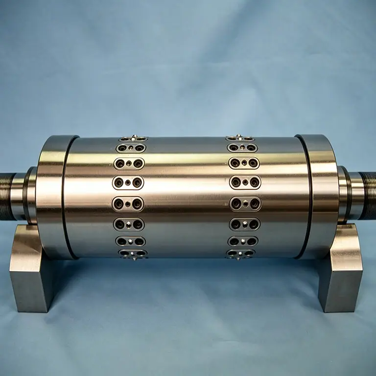
Segment fixing and preload
The fixing-hole pattern that clamps each cutting segment to the reusable body. Segment preload and height matching here are what remove shadow marks at the joints.
Custom profile
Free-form contour cutting
An irregular free-form contour machined into a solid cylinder — the kind of profile that cannot be built from straight rules, so it has to be engraved or milled as one body.
Which construction family fits your job?
If your situation is…
Choose
Because
Repeated pattern or shape contour, high volume
Solid engraved
Stable one-piece body; tightest cut-depth window
Contour split, or a segment you may need to replace
Segmented
Repairable, and each segment can use its own grade
Corrugated board above ~2 mm caliper
Segmented (solid body)
Segments carry the load; body is reused
Face length beyond 650 mm
Segmented, subject to review
Built in sections; send the drawing for a feasibility check
Fine-pitch contour with thin tooth roots
Solid engraved in PM23
Uniform carbide structure resists micro-chipping
Continuous cross-cutting or perforating
Spiral cutting
Progressive cut keeps peak force low on thin webs
Register must be held against print stations
Gear-driven
Gear and contour cut from one datum
Several slits at exact widths in one pass
Slitting blade assembly
Rings set to finished width; individually replaceable
Replacing an existing tool in a press station
Complete roller
Supplied with journals, balanced and ready to mount
Swipe the table sideways to see every column →
Rotary Die Applications We Manufacture
The same tooling family behaves differently depending on what it cuts. These are the application groups that drive our geometry, bevel and material choices.
Pressure-Sensitive Label Converting
Kiss-cutting the facestock and adhesive while leaving the liner intact, then stripping the waste matrix.
Substrates
Self-adhesive paperBOPP / PET film labelsLinerless stock
What we engineer for this
Kiss-cut at 0.02-0.05 mm penetration into the liner · multi-tooth registration · vacuum or pin slug control
W6Mo5Cr4V2 / W6Mo5Cr4V2Co5 solid engraved or gear-drivenTechnical guide →
Folding Carton & Paperboard
Through-cutting the blank, creasing the fold lines and nicking the sheet so it stays together until the folder-gluer.
Substrates
Folding carton board 200-600 gsmCoated and recycled boardLiquid-packaging board
What we engineer for this
Combined cutting and creasing on one cylinder · nick and tie optimisation · crease matrix matched to board caliper
Male and female tooling pinned together for creasing, zero-clearance burst-cut profiles and slug removal — where a single cylinder cannot produce the shape.
Substrates
Heavy boardCompositesSpecialty laminates
What we engineer for this
Pinned register between die and anvil · matched clearance held to micron level · anvil re-cut in step with the die
W2Mo9Cr4VCo8 / PM23 die · matched anvil in the same classTechnical guide →
Manufacturing Capability
What we can hold, and how we verify it. Tolerance figures are the values we hold in normal production and verify per die — not best-case laboratory results.
Parameter
Capability
Notes
Die outside diameter
Φ25 - Φ200 mm
Below Φ25 on request, subject to segment feasibility
Face length
up to 650 mm
Longer dies require a feasibility review
Radial runout of cutting edge
≤ 0.01 mm
Indicated on V-blocks, chart supplied
Tooth height tolerance
≤ ±0.005 mm
Profile projector / CMM
Cutting edge hardness
HRC 60 - 66 by grade
Rockwell, three positions per die
Hardness uniformity
±1 HRC
Vacuum gas quench, no decarburization
Gear quality
AGMA 8-10 equivalent
Matched pairs, backlash measured
Dynamic balance
≤ G6.3
Balancing machine after grinding
Surface finish on cutting edge
Ra 0.6 - 0.2 µm
Profilometer
Accepted drawing formats
dwg / dxf / pdf / stp / step / stl / iges
Feasibility review before production
Typical lead time
7 - 15 business days
Rush service available on request
Inspection documentation
Inspection report + MTC per die
Traceable to heat number
Swipe the table sideways to see every column →
Related Tooling & Lifecycle Services
A rotary die only performs as well as the components around it.
Anvil Cylinders
The counterpart cylinder that supplies cutting pressure and defines cut depth. Polished and hardened so the edge does not emboss into it — and re-ground in step with the die so the pressure window stays constant.
Hardened and polished · high roundness · re-ground as a matched set with the die
Drive & Registration Gears
Precision gears mounted on the die ends that keep the die in register with the anvil and the print stations. Backlash and tooth-to-tooth error show up directly as cut-depth variation across the web.
Matched-pair gears · minimal backlash · supplied with the die so register is repeatable
Creasing Matrices & Counter Plates
The channel that forms the crease on the reverse side. Crease width must match board caliper; too narrow and the board cracks, too wide and the fold will not form.
Matched to board caliper · counter plate supplied with the die
Resharpening & Refacing
Re-grinding the cutting edge to restore geometry while removing the least possible material from the outside diameter. Documented so you know exactly how much life remains.
Recorded outside-diameter log per die · matched anvil re-cut · segment replacement
Dynamic Balancing
Rotary dies run at high surface speed. Residual imbalance shows up as vibration, cut-depth ripple and premature bearing wear, so every die is balanced after machining.
Balance grade ≤ G6.3 · re-verified after repair
Coatings & Surface Treatment
Hard chrome, ceramic or DLC-type coatings applied to reduce wear and stop sticky materials from building up on the rake face — particularly useful on adhesives and mineral-filled board.
Hard chrome / ceramic / low-friction coatings · corrosion protection for humid climates
Customization Process · 8 Steps to Delivery
From drawing to finished die — fully transparent and traceable
01
Drawing & Requirement Intake
Send the die drawing or 3D model together with substrate, board caliper, press make and model, and target run length.
Accepts dwg / dxf / pdf / stp / step / stl / iges
02
Feasibility & Construction Review
We confirm the construction family, tooth profile, bevel and register concept — and tell you before quoting if a different construction would serve you better.
Rotary die cutting is a continuous process. The cutting tool is mounted on a rotating cylinder that runs in register with a second cylinder — the anvil — and the web or sheet passes between them. Because the tool never stops and never lifts, throughput is far higher than flatbed die cutting, and cut depth is set once by the gap between the two cylinders rather than re-established on every stroke.
The three interfaces that decide cut quality
1Tool-to-anvil gap. The single most important setting on the press. Too tight and a kiss-cut becomes a through-cut that damages the liner; too loose and the adhesive does not separate cleanly, leaving labels that will not peel. On a well-made die this gap stays stable across the full face width because the cylinder is ground concentric and dynamically balanced.
2Gear registration. The die and anvil carry matched gears so the cutting edge lands in the same place on every revolution. Backlash and tooth-to-tooth error appear as a periodic ripple in cut depth — which is exactly why gears are cut as matched pairs and the die contour is cut from the same datum as the gear.
3Contour and bevel geometry. The cutting edge is not a knife in the household sense. Its bevel angle governs how much force is needed to penetrate, how much the substrate compresses before it severs, and how long the edge survives. Tough substrates are cut with a steeper bevel so they cannot stretch before they release; soft films are cut with a shallower edge to keep cutting force, and therefore heat, low.
Cutting modes: kiss-cut, through-cut, perf and score
Mode
What it does
Typical use
What can go wrong
Kiss-cut
Cuts facestock and adhesive; liner stays intact
Pressure-sensitive labels, adhesive parts
Too deep damages the liner; too shallow leaves adhesive strings
Through-cut
Severs every layer including the liner
Separate parts from a web
Liner damage and part loss during matrix stripping
Perforation
Defined bridges hold the part in place
Tear-off lines, venting, easy-open
Bridge width must match web tension or the part tears out
Score / crease
Forms a fold line without severing
Cartons, folders, corrugated blanks
Wrong crease width for the caliper cracks the board
Nicking
Small uncut bridges across a cut contour
Keeps blanks in the sheet until the folder-gluer
Nick size unbalanced — sheet falls apart or will not separate
Swipe the table sideways to see every column →
Where the die steel's properties actually show up
A rotary die is a cutting tool that runs continuously at speed, so its failure modes are thermal and fatigue-driven rather than the pure abrasion you see on a punch. Three material properties therefore dominate:
Red hardness — how hot the cutting edge can get before it softens. This is why cobalt grades (M35, M42) exist, and why they matter most on high-speed lines cutting abrasive board.
Edge toughness at hardness — a fine-pitch contour with thin tooth roots fails by micro-chipping long before it fails by wear. ASP23's powder metallurgy structure, with carbides under 3 µm and no segregation, is the standard answer.
Hardness uniformity — ±1 HRC along the die means the whole face wears at the same rate. Uneven hardness shows up as one section of the web cutting through while another barely kisses, and it cannot be tuned out at the press.
Why we machine dies from hardened bar
We start from the same die-grade hardened round bar we sell: vacuum hardened to 0.1–1 Pa with hardness held to ±1 HRC and decarburization to ≤0.05 mm, then machined and ground with the gear and contour cut from a single datum. Starting from certified material rather than sending a soft blank out for heat treatment is what makes a ±0.01 mm runout figure repeatable from die to die instead of a lucky result.
The questions converters and die shops ask us most often when specifying rotary tooling.
What is the difference between a solid engraved die and a segmented die?
A solid engraved die has the cutting contour machined directly into a one-piece hardened steel cylinder, so there is no joint to move and cut depth is inherently repeatable. A segmented die mounts individual hardened cutting segments on a reusable steel body, which makes intricate or long contours manufacturable and lets you replace one damaged section instead of re-machining the whole cylinder. Solid dies hold the tighter cut-depth window; segmented dies are more repairable.
When should I choose a segmented rotary die?
Choose segmented tooling when the contour is too intricate or too long to machine as one piece, or when you want repairability. Segmented dies mount individual hardened cutting segments on a reusable steel body, so a damaged or worn section is replaced or re-ground off the machine instead of remachining the whole cylinder. They are the standard answer for corrugated board.
What is a spiral cutting rotary die used for?
Spiral and helical dies are used for continuous cross-cutting, perforating and slitting of web material. Because the cutting edge is helical, the cut is progressive rather than simultaneous across the full face, so peak cutting force is much lower. That lets you run thin or brittle webs at higher line speed without the web snapping, and it produces less noise and vibration than a straight cross-cut.
Why does the drive gear matter so much on a rotary die?
The gear sets the die's angular position against the anvil and the print stations, so any error between the gear teeth and the cutting contour shows up as a cyclic variation in where the edge lands. At high speed that becomes cut-depth ripple — one label cut perfectly and the next cutting through its liner. This is why the gear and the contour are cut from a single datum on the same machine, and why gears are supplied as matched pairs.
What is the difference between kiss-cutting and through-cutting?
Kiss-cutting penetrates the facestock and adhesive but leaves the liner intact, so the parts stay on their carrier — this is how pressure-sensitive labels are made. Through-cutting severs every layer including the liner, producing separate parts. The difference is a matter of microns in cut depth, which is why a rotary die that holds a tight cut-depth window matters more than its headline hardness.
Which steel grade should a rotary die be made from?
It depends on the failure mode and the run length. Use W6Mo5Cr4V2 for general high-speed rotary cutting because it has the best toughness of the HSS grades. Move to W6Mo5Cr4V2Co5 for long board and label runs where edge temperature shortens life, and to W2Mo9Cr4VCo8 for abrasive film and thick board. Choose PM23 where a fine-pitch contour micro-chips — its powder metallurgy structure has carbides under 3 µm with no segregation, which removes the initiation sites for chipping. Cr12Mo1V1 and Cr8Mo2SiV cover the mid-range: Cr12Mo1V1 is the D2 / SKD11 workhorse, Cr8Mo2SiV the tougher upgrade.
How many times can a rotary die be resharpened?
That depends on how much outside diameter the tool can afford to lose before the tooth height or the gear relationship becomes unusable. A solid die is normally ground in steps of 0.05-0.10 mm off the radius, with several regrinds available over its life. Every regrind is logged against the die's outside-diameter record, so you always know how much life remains. Segmented dies are cheaper to keep alive because individual segments can be replaced rather than the whole body.
What information do you need to quote a rotary die?
Send the die drawing or 3D model, the substrate and its caliper or grammage, the press make and model, the anvil diameter, the target run length between resharpens, and the line speed. If you have run the job before, the previous die's outside diameter and its resharpening log are extremely useful, because they tell us how much tolerance margin the existing setup has.
Do you also supply the anvil and gears?
Yes. A rotary die performs as well as the components around it, so we supply matched anvil cylinders and drive gears cut as pairs to minimise backlash. When a die is refaced, the matching anvil is re-ground in step so the pressure window stays where it was on the day the die was new.
What tolerance can you hold on the cutting contour?
Radial runout of the cutting edge is held to 0.01 mm or better and tooth height to ±0.005 mm, verified on a profile projector or CMM. These figures matter more than they look: at high web speed a runout error turns directly into cut-depth ripple, which is what causes intermittent kiss-cut failures and liner damage.